

How to Perform a Circuit Breaker Timing Test: Step-by-Step Procedure
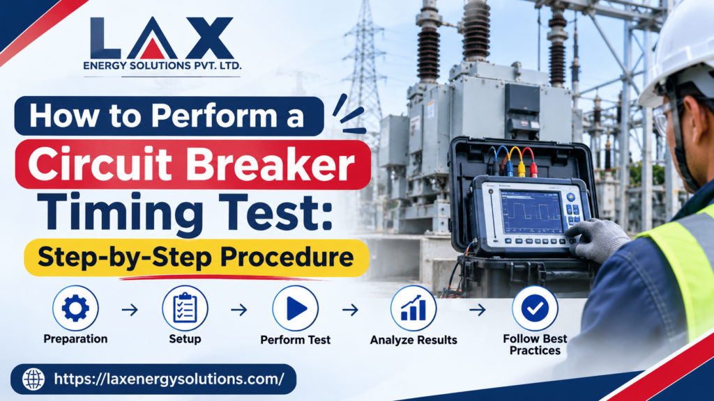
Picture a feeder fault. The relay picks it up within a few cycles and sends a trip command, and then everything depends on the breaker doing its job in the time it was designed to. If the opening time has drifted, or one pole lags behind the others, the protection scheme performs worse than anyone assumes, and nothing visible on the breaker will tell you. A circuit breaker timing test closes that gap. It measures how long the contacts take to open and close, pole by pole, and exposes mechanical or operational problems before they cause a failed operation.
This guide is for engineers and technicians who already know switchgear basics and want a practical walk-through: what the test is, the equipment, the step-by-step circuit breaker timing test procedure, how to read the results and the mistakes that spoil them.
What Is Circuit Breaker Timing Testing?
It is an electrical test that measures, in milliseconds, how long a breaker’s contacts take to separate after a trip command (opening time) and to make after a close command (closing time), separately for each pole.
The instrument starts a clock when the command is issued and stops each channel when its contacts change state. This circuit breaker contact timing gives a precise picture of how the operating mechanism is behaving, which a visual inspection can’t.
The test earns its place at several points in a breaker’s life:
- Commissioning: confirming the breaker matches factory and site acceptance values
- Preventive maintenance: trending performance from one outage to the next
- Troubleshooting: investigating a failed or unexplained operation
- Condition assessment: informing refurbishment or replacement decisions
Consistency between poles matters as much as the absolute times. Three-phase equipment is designed on the assumption that all poles switch almost together. A wide spread can point to uneven mechanical operation, linkage wear or a drifted adjustment, and in service it can stress connected equipment.
Why Is Circuit Breaker Operating Time Testing Important?
A breaker can look perfectly healthy and still be slow. Timing data gives you evidence instead of assumptions:
- Verifies performance: opening and closing times are checked against the manufacturer’s specification.
- Detects pole-to-pole variation: a single overall figure would hide it.
- Flags mechanical issues: friction, weakened springs, lubrication problems or worn latches often show up first as drifting operating times.
- Assesses switching behaviour: including contact bounce, where the instrument can capture it.
- Supports circuit breaker maintenance testing: each breaker builds a documented history.
- Protects reliability: degradation is found before it becomes a failure to operate.
It complements, rather than replaces, other electrical switchgear testing such as contact resistance and insulation checks.
Equipment Required for Circuit Breaker Timing Testing
Circuit breaker testing equipment varies with breaker design, voltage class, test configuration and instrument capability. A typical set-up includes:
- Circuit breaker timer or compatible analyser: records the command and contact events on every channel
- Timing measurement leads: carry the contact signals; their condition directly affects reliability
- Control cables: let the instrument issue or monitor trip and close commands
- Connection probes and accessories: clamps and adapters that give a firm, clean connection
- Auxiliary power supply, where required: a stable source at the rated control voltage
- Travel transducer, if needed: adds travel and velocity analysis alongside timing
- Documentation and safety equipment: wiring diagrams, manufacturer specifications, PPE, earthing equipment and lock-out devices
Circuit Breaker Timing Test Procedure: Step-by-Step Guide
Safety warning: only qualified personnel should perform this work, on a breaker that is de-energised, isolated and earthed under your site’s approved procedure. This is a general outline, not a method for every breaker. Where it differs from the manufacturer’s instructions, follow the manufacturer.
Step 1 – Review Circuit Breaker Specifications
Start with the manufacturer’s documentation. Note the breaker type and operating mechanism, the rated control voltage, the required operating sequences, and the specified opening, closing and close-open times, including permitted pole spread. Keep previous test reports handy; they are your best comparison.
Step 2 – Ensure Proper Safety and Isolation
De-energise and isolate the breaker from every source, apply lockout/tagout (LOTO) and earth it as site procedure requires. Respect stored energy: a charged spring or hydraulic mechanism can operate unexpectedly. Read any manufacturer-specific instructions before connecting equipment.
Step 3 – Prepare the Circuit Breaker Timer
Inspect the timer, leads and accessories for damage and confirm calibration is current. Check that the channel count and connections suit the breaker’s poles and interrupters. Then configure the instrument and select the measurement mode the test needs, as its manual describes.
Step 4 – Connect the Timing Measurement Leads
Connect one timing channel across each pole so every phase is recorded separately, then connect the control circuit so the instrument can issue or monitor the commands. Follow both manufacturers’ wiring diagrams and double-check every clip. A swapped lead can look exactly like a mechanical fault.
Step 5 – Perform the Opening Time Test
How do you measure circuit breaker opening time? With the breaker closed, issue a trip command. The instrument starts timing at the command and stops each channel as its contacts separate. That interval is the circuit breaker opening time, recorded in milliseconds because protection performance depends on very short intervals. Record every pole individually, plus the trip coil used.
Step 6 – Perform the Closing Time Test
How is circuit breaker closing time measured? With the breaker open, issue a close command and record the time until each pole’s contacts make. That interval is the circuit breaker closing time. Compare the poles straight away, because circuit breaker pole synchronisation problems usually show here.
Step 7 – Perform Close-Open and Additional Tests
A close-open (CO) timing test sends a close command followed by an open command after a short, deliberate delay, testing how quickly the mechanism can reverse. Other sequences may apply depending on the breaker. If your instrument supports it, also record auxiliary contact timing and contact bounce.
Step 8 – Analyse and Record Test Results
Compare measured values with manufacturer specifications and applicable standards such as IEC 62271-100. Evaluate pole-to-pole differences, look for unusual scatter between repeated operations and note the control voltage used. Store results with breaker ID, date and instrument details so future tests compare like with like.
How to Interpret Circuit Breaker Timing Results?
There is no universally acceptable value. Limits depend on the breaker’s design and rating, applicable standards and the manufacturer’s recommendations, so always compare measured values with the specified ones and investigate meaningful differences.
Parameter | What It Measures | Why It Matters |
Opening time | Trip command to contact separation | Shows how quickly the breaker can interrupt current |
Closing time | Close command to contact engagement | Reflects closing mechanism performance |
Close-open time | Contact making to the next separation in a CO operation | Confirms the mechanism can reverse quickly |
Pole spread | Time difference between poles | A large gap may mean uneven mechanical operation |
Contact bounce | Brief re-opening after first making | May point to mechanical or contact problems |
One reading tells you little. Times that creep upward across several tests deserve attention, even while they stay inside limits.
Common Mistakes to Avoid During Breaker Timing Tests
- Incorrect lead connections: reversed or misplaced channels give misleading pole data.
- Incompatible equipment: the instrument must suit the breaker and its control circuit.
- Ignoring manufacturer specifications: generic limits lead to wrong pass or fail calls.
- Wrong control voltage: operating times change with coil voltage, so test at the specified value.
- Weak isolation and safety: the most serious error of all.
- Missing pole data: a single overall figure hides synchronisation problems.
- Misreading results: ignoring test conditions or earlier reports leads to wrong conclusions.
- Skipping calibration and checks: unreliable measurements undermine everything that follows.
How Does a Circuit Breaker Timer Help Improve Testing Accuracy?
A circuit breaker timer logs the command and each contact event together, so every pole is measured within the same operation. Accurate opening and closing times matter because small errors can hide the very drift you are looking for. A suitable instrument also supports maintenance documentation, so results can be compared across years and between similar breakers.
Available measurement features, such as channel count, resistor-contact support, bounce capture and travel input, vary by instrument model, so match the instrument to the breakers you maintain.
Conclusion
Regular circuit breaker timing test campaigns give maintenance teams hard evidence of how a mechanism is aging. Following the correct circuit breaker timing test procedure, with attention to specifications, safety, connections and records, produces results you can trust and trend. Suitable equipment matters just as much, because it determines how reliably opening, closing and close-open operations are captured.
If you are building out your switchgear testing toolkit, explore the circuit breaker timing solutions from Lax Energy Solutions Pvt Limited.
Frequently Asked Questions
What is the purpose of timing a circuit breaker?
To confirm that contacts open and close within the intended time and that all poles operate consistently.
How is the test performed?
After isolation and earthing, you connect a timing channel to each pole and the control circuit, then record opening, closing and close-open operations.
What equipment is required?
A circuit breaker timer or analyser, leads, control cables, accessories, an auxiliary supply if needed, and safety equipment. A travel transducer is optional.
How do opening and closing time differ?
Opening time runs from the trip command to contact separation. Closing time runs from the close command to contact engagement.
What is close-open timing?
It is a close operation followed immediately by an open command, showing how quickly the mechanism can reverse.